Measurement · Entry 07.1
Field strength
Coverage is measured, not calculated — a meter, a route and a map of readings.
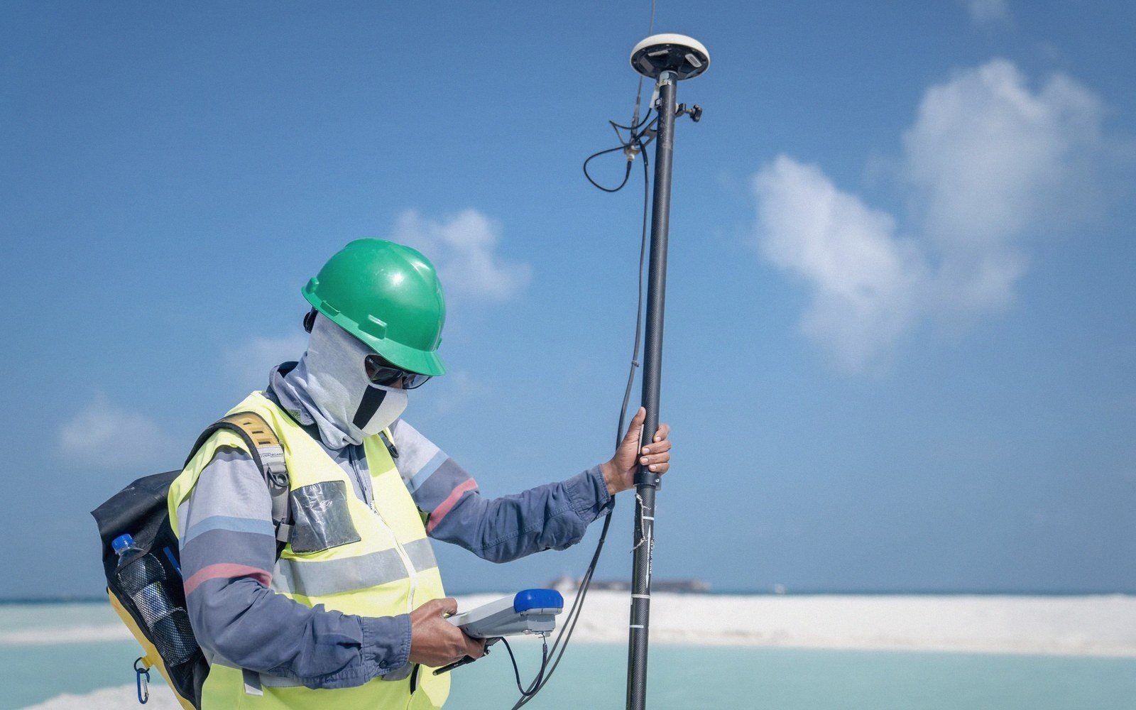
A meter, a calibrated antenna, and a route — the only way to know what a signal actually does in the real world.
The Number Behind the Contour
Field strength is the electric field intensity of a radio wave at a given point — measured in millivolts per metre (mV/m) or, for weaker signals, microvolts per metre (µV/m). It is the quantity that actually links the transmitter to the receiver: a tuner responds to field strength, an interference calculation depends on it, and a coverage contour drawn on a map is a line connecting points of equal predicted field strength. Predicted — that word does the work. Terrain, soil conductivity, buildings, and the precise height of the antenna all bend the real-world result away from the idealized curve. Coverage is measured, not calculated, because calculation alone is never enough.
| What | The consequence |
|---|---|
| mV/m and µV/m | the standard units of field strength; mV/m for strong ground-wave signals, µV/m for distant or attenuated paths |
| Standard measurement height | 1 metre above ground for AM ground-wave surveys |
| Radial spacing | readings typically every ½–1 mile; more frequent near the tower, sparser at distance |
The ground wave attenuates with distance in a way that depends heavily on what the signal passes over. Sandy soil, seawater, and saturated clay conduct differently; each produces a different attenuation curve. The FCC's standard propagation curves — derived from decades of empirical data — capture the median behavior, but they cannot know what your specific path crosses. A measured field-strength survey fills that gap.
What Measurement Actually Involves
The instrument is a calibrated field-strength meter: a selective voltmeter tuned to the carrier frequency, connected to a receiving antenna of known effective length. The antenna — often a shielded loop for AM, a calibrated dipole or discone for FM and higher frequencies — is set to a standard height, typically one metre above the ground for AM surveys. The meter converts the voltage at its terminals into a field-strength figure by factoring in the antenna's known sensitivity. Accuracy depends on that calibration holding; a meter drifts, so pre- and post-survey calibration checks against a reference source are standard practice.
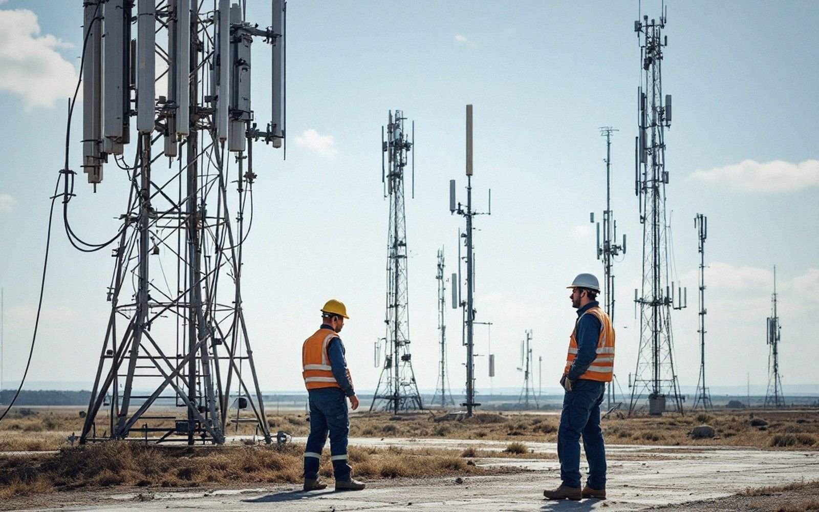
The field engineer drives a radial route away from the tower, stopping at measured intervals — often every mile, sometimes every half-mile near the site — to take a reading. At each point the GPS position is logged, the meter reading is noted, and the result is mapped. The full proof of performance for a directional AM array requires multiple radials, fanning out in the directions the licence specifies, because the station's pattern must be verified in every bearing where a limit or a protection requirement applies. A non-directional station still needs measured radials; it simply needs fewer of them.
Each reading is an instantaneous sample, which introduces its own complication. AM signals fade — the ground wave is relatively stable by day, but skywave contamination at night causes the received signal to fluctuate over a matter of seconds. Night-time measurements must therefore be averaged: the engineer parks, waits, and logs a sufficient set of readings to get a meaningful mean. The International Telecommunication Union's measurement guidelines formalize this, specifying averaging periods and acceptable variance, because a single noisy peak or trough tells you nothing reliable about the field at that point.
| What | The consequence |
|---|---|
| Calibrated field-strength meter | selective voltmeter plus antenna of known effective length |
| GPS position log | every reading tied to a coordinate |
| Night-time averaging | multiple readings per point to average out skywave-induced fading |
| Multiple radials | directional arrays require readings on every bearing specified in the licence |
Why the Number Matters Operationally
Field strength is not only an engineering curiosity — it has regulatory weight. The FCC sets minimum field-strength requirements for a station's service contour and maximum limits for interference into a protected station's contour. If a measured value falls short of the required service-area figure, the station may need more power, a better ground system, or a taller antenna. If a measured value at a co-channel or adjacent-channel station's boundary exceeds the interference limit, the transmitter must reduce power or reorient its pattern. The numbers from the field survey are what the licence is actually checked against.
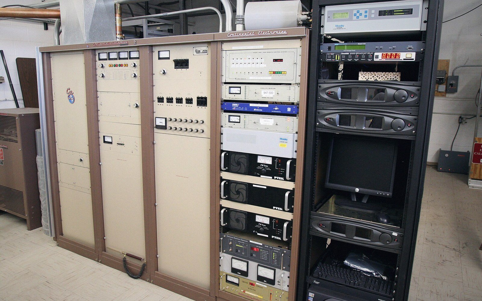
There is also a subtler value. Measured data reveals anomalies — a surprising null from terrain diffraction, a reflection off a water tower boosting signal into a dead zone, salt-marsh conductivity lifting readings higher than the standard curves predict. None of these appear in a desk calculation. The meter, the route, and the map of readings are how an engineer learns what a transmitter actually does, rather than what the textbooks say it should. That gap between prediction and measurement is where real transmission engineering lives.