Propagation · Entry 01.1
Ground wave
The signal that follows the curve of the earth, and why soil conductivity decides how far it gets.
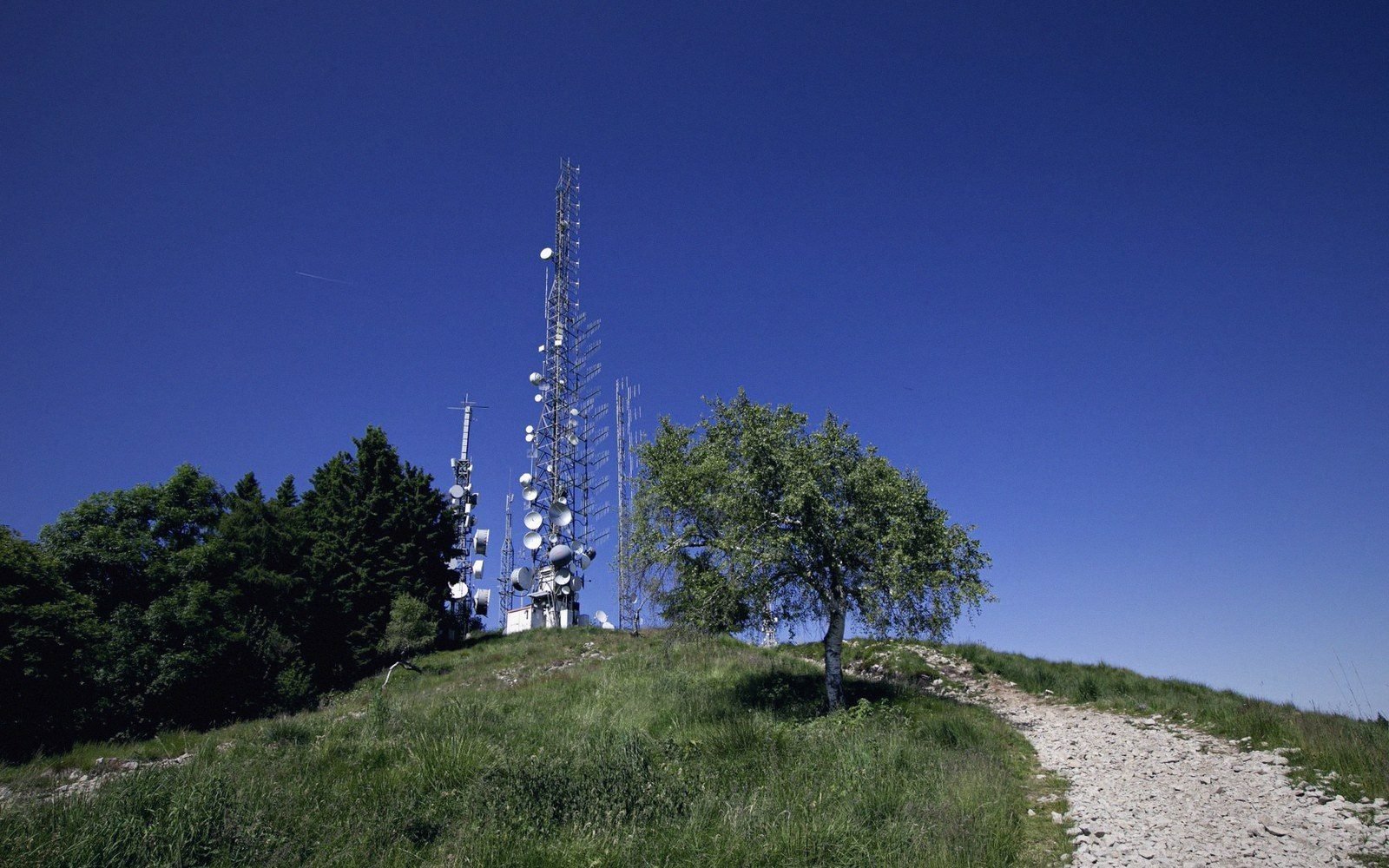
The signal that stays earthbound — and why soil conductivity decides how far it gets
A medium-wave transmitter radiates in all directions, but the signal that delivers reliable daytime coverage is not the one heading skyward. It is the one that travels along the surface of the earth, bending around the planet's curvature through a process called diffraction. That surface-following component is the ground wave, and its reach is determined less by transmitter power than by what the ground beneath it is made of.
The mechanism works because the lower edge of a radio wavefront is slowed by contact with the earth's surface. The wavefront tilts forward, wrapping itself around the curve of the ground rather than shooting off into space. The better the earth conducts electricity, the less energy the wave loses to that surface as it travels. Poor conductors — dry sand, granite bedrock, mountainous terrain — absorb energy rapidly, trimming the useful range to a few tens of kilometres even at high power. Seawater, with a conductivity roughly a thousand times greater than average soil, sustains a ground wave across hundreds of kilometres. This is why long-wave and medium-wave broadcast coverage maps are not circles: they follow the terrain's electrical character, not its geometry.
| What | The consequence |
|---|---|
| Conductivity | seawater (~4 S/m) carries the wave far; dry rock or sand (~0.001 S/m) kills it fast |
| Frequency | lower frequency, longer surface range; above ~3 MHz the ground wave collapses |
| Power | raises field strength, but conductivity is usually the ceiling on useful range |
| Antenna height | near 0.5–0.625 wavelengths maximises low-angle radiation for AM |
Frequency matters, too. Ground wave attenuation increases with frequency, which is why the AM broadcast band (roughly 530 to 1700 kHz in North America, 526.5 to 1606.5 kHz in the ITU Region 1 plan) works so much better for long surface-range than shortwave. At frequencies above about 3 MHz, the ground wave collapses within a few kilometres and skywave takes over as the dominant long-range mode. Below the broadcast band, at very low frequencies, the ground wave is extraordinarily persistent — the reason that naval low-frequency stations were built precisely there.
What the transmitter and ground system can do about it
The transmitter engineer cannot change the soil, but can work with it. A high-conductivity path — coastal location, river delta, heavy clay — is chosen when possible, and the antenna is sited to exploit it. Beyond siting, the radiated field strength in the horizontal plane is what drives ground-wave range, which makes antenna efficiency central. Energy wasted in ground losses in the antenna's near field is energy not carried forward. Ground radials — copper conductors buried in a star pattern around the tower base — lower those near-field losses by giving return currents a low-resistance path, directly improving the field strength the wave carries into the distance.
Tower height contributes as well, up to a point. For AM broadcasting, an antenna somewhere between 0.5 and 0.625 wavelengths tall maximises the low-angle radiation that feeds the ground wave. The BBC's transmitter at Droitwich, licensed at 500 kW on 198 kHz, takes advantage of both a well-designed ground system and low frequency to cover most of England and Wales in daylight. WLW in Cincinnati, authorised at 500 kW during its experimental period in the 1930s, demonstrated that raw power raises field strength, but that the marginal return in range is modest once the ground's conductivity is the limiting factor.
Field strength — measured in millivolts per metre at a given distance — is the engineering yardstick for ground-wave coverage. The FCC publishes propagation curves, derived from the theoretical work and empirical measurements that were refined through the mid-twentieth century, relating transmitter power and antenna efficiency to expected field strength over ground of specified conductivity. Those curves are the basis for licensing calculations in the United States; the ITU publishes equivalent material for international coordination. Both acknowledge that real terrain imposes variations the curves can only approximate.
| Where | Why it is here |
|---|---|
| Droitwich, England | BBC 198 kHz long-wave, 500 kW; classic long-range ground-wave service |
| WLW, Cincinnati | 500 kW experimental licence, 1930s; still a benchmark in transmitter power history |
| ITU Region 1 | the frequency planning zone covering Europe, Africa and the Middle East |
At night, the ground wave does not disappear, but it is no longer the story. The D layer of the ionosphere, which absorbs skywave energy during daylight and suppresses long-distance interference, collapses after sunset. Skywave returns from the F layer, and stations hundreds of kilometres away begin arriving on the same channel. The ground-wave signal that seemed perfectly clean at noon is now competing with reflections from the sky, producing the fading and distortion that defines nighttime AM reception. The ground wave itself is unchanged — the ionosphere simply stops protecting it from company.