The Mast · Entry 03.2
Ground radials
Buried copper doing half the work; a poor ground system wastes power no transmitter can make back.

The buried half of the antenna
A medium-wave tower radiates efficiently only when it has a proper ground system beneath it — and "proper" means dozens to over a hundred copper wires fanning out from the tower base in every direction, buried just below the surface. The tower gets the engineering attention; the radials do half the work in silence.
The mechanism is not mysterious. A vertical antenna drives current down into the earth as well as up into the air, and the earth is not a perfect conductor. Real soil has resistivity — sometimes very high resistivity, depending on moisture content, mineral composition and geography. Every ohm of resistance in the ground path is an ohm that dissipates power as heat instead of launching it as a radio wave. The radial system exists to short-circuit that loss by giving return current a low-resistance copper path rather than a high-resistance dirt path.
| What | The consequence |
|---|---|
| ~36 Ω | typical radiation resistance of a quarter-wave vertical antenna |
| 120 | quarter-wave radials used as the FCC reference "perfect" ground |
| Quarter-wavelength | ideal radial length (≈ 75 m at 1 MHz) |
| 1937 | George Brown's Proceedings of the IRE radial study, the foundational reference |
Physically, a radial is simply a wire — typically solid or stranded copper — laid on or just below the ground surface and connected at one end to the tower base. The other end terminates in open soil. Lengths are ideally a quarter-wavelength at the operating frequency, which for a 1 MHz (300-metre wavelength) station means roughly 75-metre wires. In practice, shorter radials still help, and more radials of moderate length consistently outperform fewer radials of ideal length: the relationship between radial count and ground loss is steep at first and flattens as the system approaches saturation. The FCC-accepted engineering standard, codified in what is now Part 73 of the Code of Federal Regulations, has long recognised 120 quarter-wave radials as a reference "perfect" ground, though many licensed installations work with fewer and compensate through careful measurement.
George Brown's landmark 1937 research — published in the Proceedings of the IRE — established empirically that the improvement from adding more radials follows a logarithmic curve. The first few dozen radials yield dramatic reductions in ground-loss resistance; radials 100 through 120 yield incrementally less. Brown's measurements remain the foundation for modern ground-system design, and no subsequent work has overturned his basic conclusions.
What poor ground costs
Ground loss resistance appears in series with the radiation resistance of the antenna. A typical quarter-wave vertical has a radiation resistance of around 36 ohms. If the ground system introduces even 10 ohms of loss resistance, roughly 22 percent of transmitter power is converted to heat before a single watt leaves as a signal. Double that loss to 20 ohms and the antenna is wasting more than a third of its input power. No transmitter, no matter how powerful, can make back what the ground system wastes.
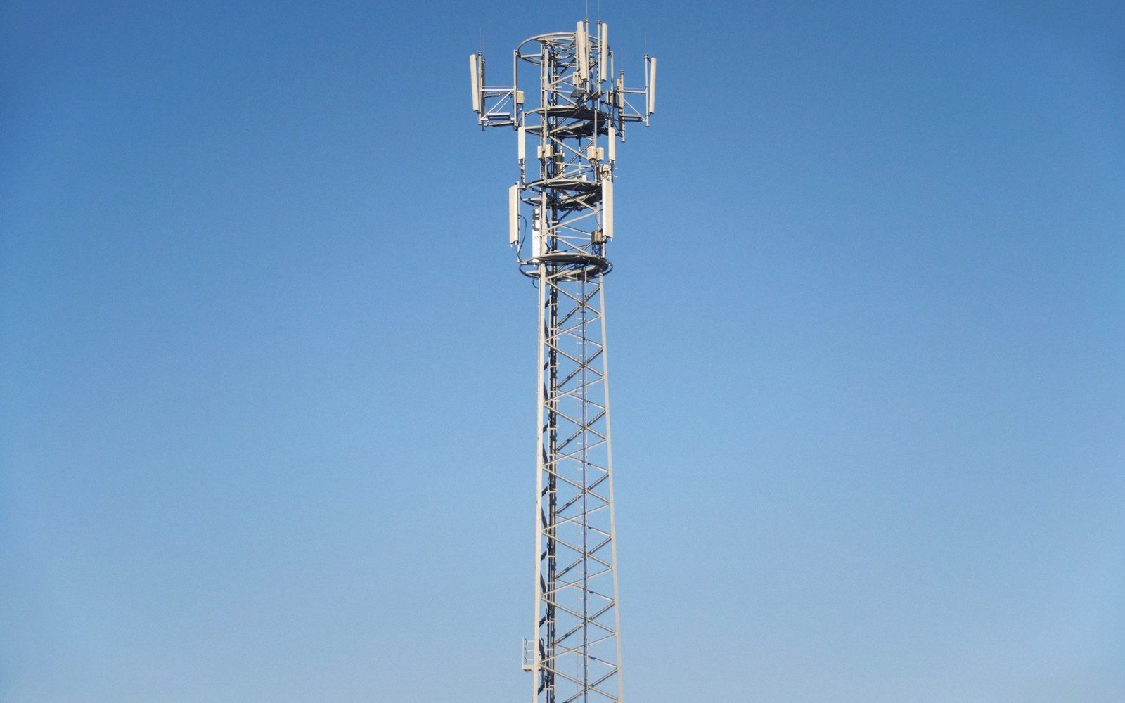
The consequence extends beyond brute efficiency. A lossy ground system also raises the antenna's feed-point impedance, complicates matching, and can introduce unpredictable behaviour in a directional array where element impedances must be held stable to maintain a licensed pattern. Ground-system degradation — wires corroding, connections failing, soil drying seasonally — is therefore a maintenance matter, not just an installation detail.
At elevated sites, a buried radial field is sometimes impractical. Engineers then use elevated radials: a small number of radials (commonly four) raised above ground level and resonated as part of the antenna system. Elevated systems can perform well, but they are sensitive to symmetry and more susceptible to interaction with nearby structures. The buried field with many radials remains the preferred solution wherever ground access permits.

Monitoring the system's health is straightforward in principle: the base current and feed-point resistance, measured during a routine proof of performance, will drift if the ground system degrades. A station that finds its antenna current falling for a given power level, with no change in the transmitter, should inspect its ground connections before looking anywhere else. The copper underground is doing half the work, and when it begins to fail, the tower above cannot compensate.