The Mast · Entry 03.1
The mast is the antenna
A series-fed tower radiates as a whole and stands on an insulator, which is why its height is chosen in wavelengths rather than metres.
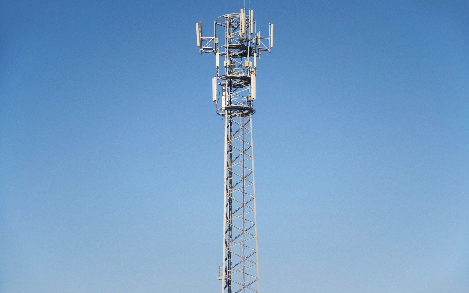
A broadcast tower does not carry the antenna — it is the antenna, and every engineering decision about it follows from that single fact.
Steel in the circuit
An AM broadcast tower is not a support structure with a transmitter at the top. It is the radiating element itself, fed at the base and standing on a single ceramic or porcelain insulator that keeps it electrically isolated from the ground. That insulator — sometimes a stack of discs, sometimes a purpose-built pedestal — carries the full structural load of a steel lattice that may weigh hundreds of tonnes, while simultaneously blocking the RF path to earth. The transmitter feeds into the tower at that base point, current flows up through the steel, and the whole structure behaves as a vertical monopole radiating in every horizontal direction.
| What | The consequence |
|---|---|
| Tower height ↔ wavelength | 0.528λ maximises horizon radiation; below 0.25λ efficiency falls; above ~0.625λ pattern tilts skyward |
| Ground radial length | ideally equal to tower height; more radials and greater extent reduce ground-loss resistance |
| Base insulator | carries full structural load while blocking the RF path to earth — failure of either function disables the antenna |
This arrangement is called a series-fed tower, because the antenna element is in series with the feed — no coaxial feed running up inside, no separate radiating element bolted on at mid-height. The tower and the antenna are the same object. That identity drives every subsequent decision: how tall, how wide, how precisely plumb, and what the ground beneath it must look like to complete the circuit.
Why height is counted in wavelengths
Because the tower is the radiating element, its electrical length determines its radiation pattern and efficiency. Engineers specify tower height not in metres but as a fraction of the operating wavelength — typically around 0.528λ, a figure that has appeared in broadcast engineering since the 1930s because it produces maximum radiation toward the horizon, which is where the audience is. A tower that is a quarter-wavelength tall (0.25λ) is simpler and cheaper but slightly less efficient. Push past about five-eighths of a wavelength and the pattern begins to tilt upward, wasting power into the sky.

At medium-wave frequencies, a wavelength ranges from roughly 180 metres (at 1700 kHz) to about 570 metres (at 530 kHz). A 0.528λ tower for a station at 1000 kHz — wavelength 300 metres — stands about 158 metres tall. That is a serious civil engineering project, and the specific number comes entirely from the physics of the radiating element, not from any desire for height. The BBC's Droitwich transmitter, serving the UK on 198 kHz with a wavelength just over 1500 metres, uses a tower well over 200 metres tall for exactly this reason; the long wavelength demands a long antenna.
The Blaw-Knox tower design — a diamond-profile lattice, broadest near the middle and balanced on a base insulator — was developed in the 1930s partly to manage the capacitance distribution along a tall radiating element, improving current distribution and thus radiation efficiency. Shape is not aesthetic; it is electrical.
Chronology of key decisions
- 1930sBlaw-Knox develops the diamond-profile lattice tower to improve current distribution on tall radiating elements
- 1930s–40sSeries-fed tower becomes the dominant AM broadcast antenna form, replacing top-loaded and other configurations
- OngoingITU and FCC codify minimum ground-system standards as licence conditions
The ground system closes the circuit
A vertical monopole over perfect ground behaves as if it were one half of a full-length dipole, with the earth acting as a mirror to complete the other half. Real ground is not perfect, and its losses directly reduce the power that actually leaves the antenna as useful radiation. The solution is a buried ground radial system — copper wires running outward from the tower base in all directions, typically to a distance equal to the tower height, and sometimes further. These radials make the effective ground resistance low enough that most of the transmitter's power goes into the air rather than into soil heating.

The ITU and national regulators, including the Federal Communications Commission in the United States, specify minimum ground systems as a licensing condition because a poorly grounded tower is effectively a power-wasting device. A station running 50 kilowatts into a compromised ground system may radiate less usable signal than one running 10 kilowatts into a properly engineered installation.
When a directional array is built — multiple towers fed with controlled phase differences to protect another station or fill a particular service area — every tower in the array is a series-fed radiating element subject to the same physics. The heights, the ground system and the base insulator design must be consistent across all elements, because any asymmetry changes the current distribution and therefore the pattern. Proof of performance measurements exist precisely because the pattern that emerges from a real array of real towers in real ground must be verified, not assumed.