The Array · Entry 04.1
Phase and pattern
Two or more towers fed with a controlled phase difference produce a pattern that protects one direction and reinforces another.
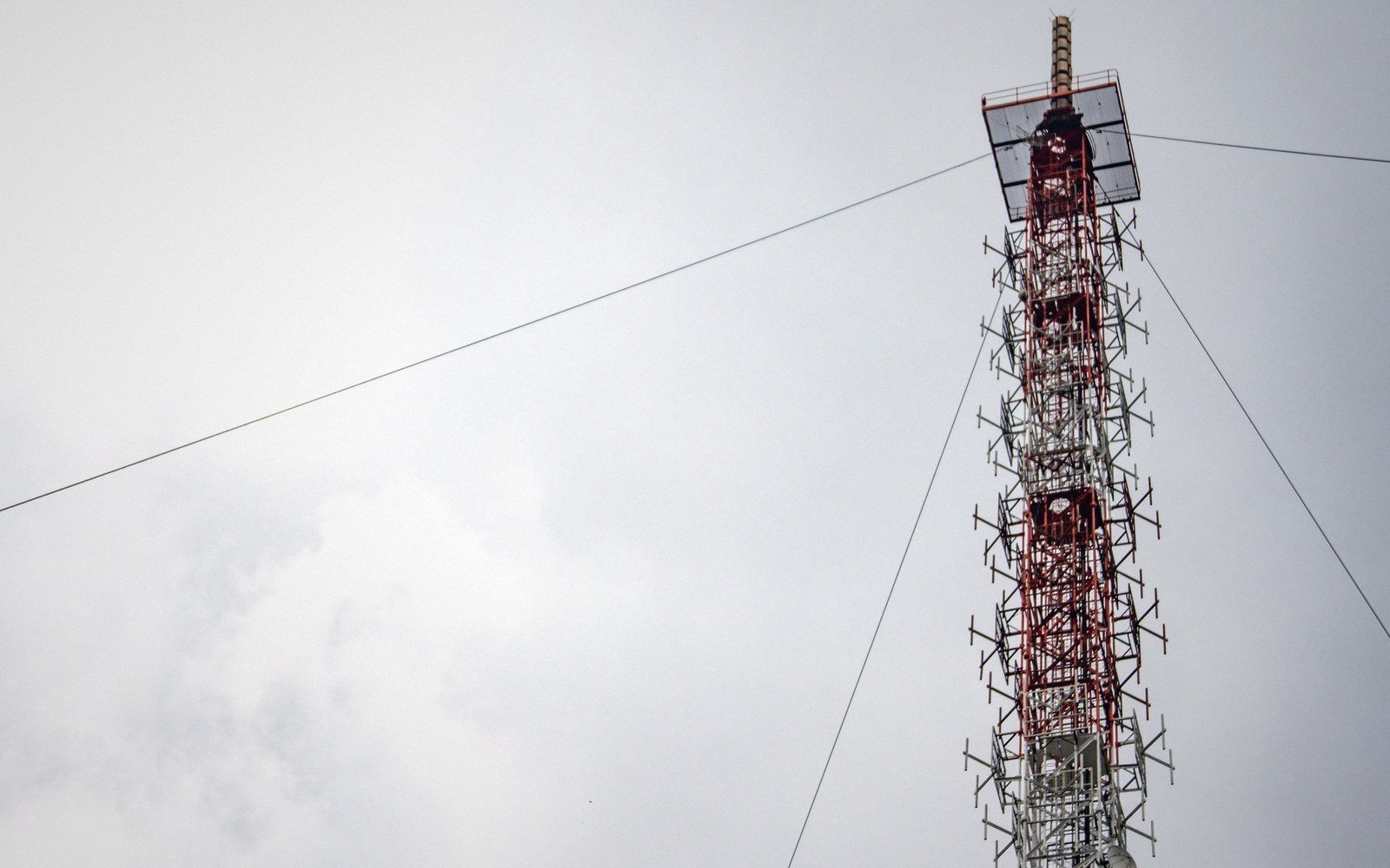
Feed two towers the same signal and you get two transmitters. Shift the phase between them and you get a weapon aimed in one direction and silenced in another.
Why phase shapes the field
A single tower radiates in all directions equally — a perfect circle on the map. Add a second tower a quarter-wavelength away, feed it with the same amplitude but a 90-degree phase lag, and the two fields now add in one direction and cancel in the opposite one. The arithmetic is straightforward: where the signals arrive in phase, field strengths sum; where they arrive 180 degrees apart, they subtract toward zero. Change the spacing, the phase offset, or the amplitude ratio between towers and you reshape the pattern entirely.
How the pattern forms — key relationships
- Equal towers, same phase, spacing very small compared with a wavelength — near-omnidirectional (circle)
- Equal towers, 90° phase, quarter-wave spacing — cardioid (one null, one reinforced lobe)
- Equal towers, 180° phase, half-wave spacing — figure-eight (two nulls perpendicular to the array axis, two lobes along it)
- Amplitude ratio ≠ 1 — null depth reduced; lobe asymmetry introduced
- More towers — more degrees of freedom to shape multiple nulls simultaneously
This is the operating principle behind every directional medium-wave array: a null aimed at a city or another station's service area, a lobe aimed at the population you want to reach. The Federal Communications Commission has required directional arrays on the medium-wave band since the 1930s precisely because the band ran out of room; protecting a co-channel station hundreds of miles away means engineering a quiet direction toward it, day and night.
Building the pattern from phasors
Engineers describe each tower's contribution as a phasor — a quantity with both amplitude and phase angle. The phasor for tower one is typically the reference, set at zero degrees. Every other tower is expressed relative to it: perhaps 0.7 times the amplitude at 90 degrees, or equal amplitude at 137 degrees. The total field at any bearing is the vector sum of all the individual tower contributions at that bearing, each adjusted for the geometry of the array and the electrical ground between them.
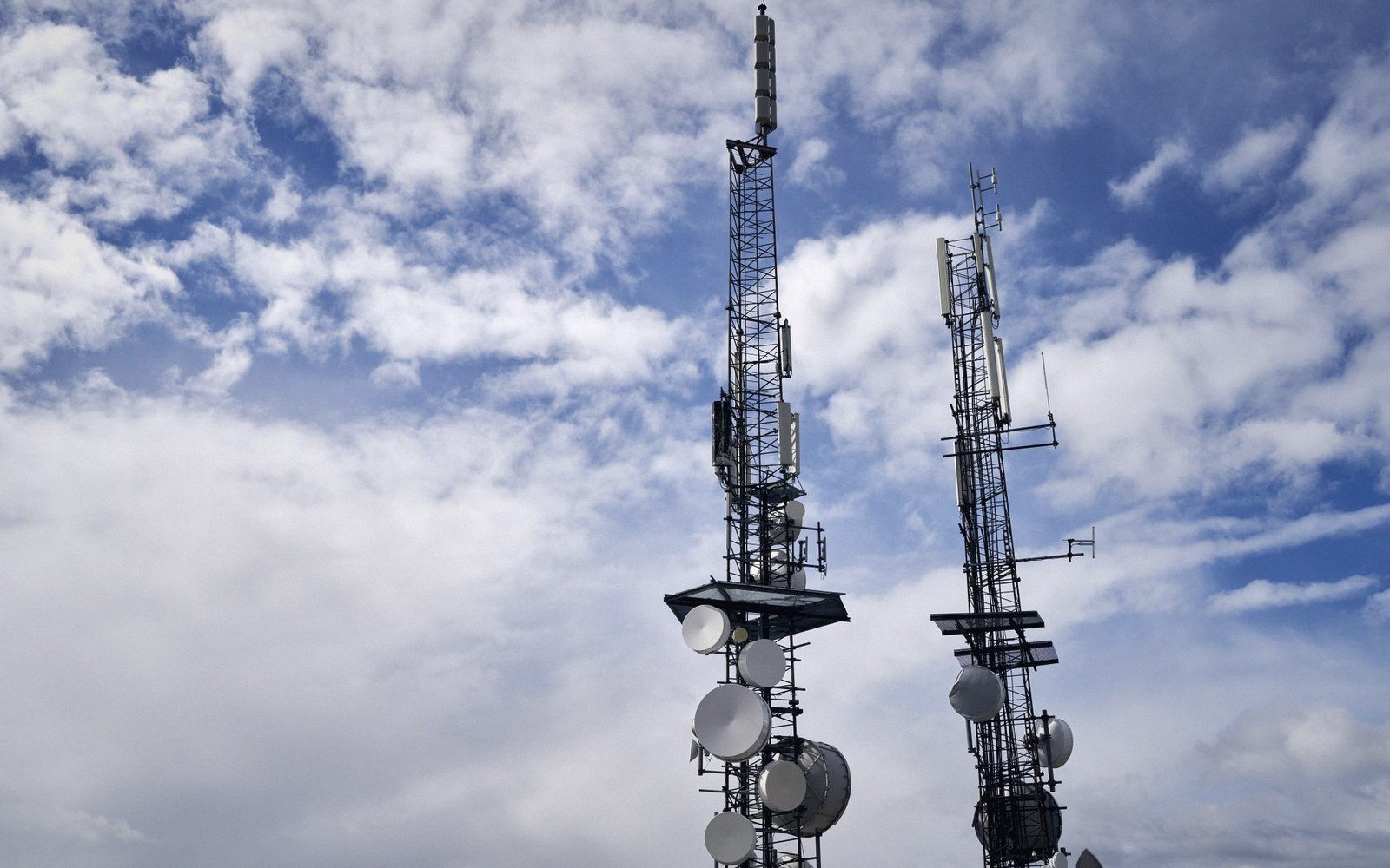
Spacing matters enormously. Quarter-wave spacing between two equal towers fed 90 degrees apart produces a cardioid — reinforced in one direction, a deep null in the other. Half-wave spacing with 180-degree phasing produces a figure-eight with two lobes and two nulls at right angles to the line of towers. Three and four-tower arrays allow the engineer to sculpt patterns with multiple protected azimuths and carefully shaped lobes, trading depth of null in one direction for directional gain in another. The phasor cabinet — a network of power dividers, inductors and capacitors — is what actually delivers those amplitude and phase values to each tower's feed point.
Ground, coupling and what can go wrong
The pattern exists in theory the moment you write down the phasors. It exists in practice only if the transmission lines to every tower are stable, the ground system beneath each tower is electrically consistent, and the towers are not coupling energy into each other through the soil. Mutual impedance between closely-spaced towers is real and significant; the current that flows in tower one induces a voltage in tower two, altering the actual current distribution unless the phasing network is designed to compensate. A well-designed array accounts for mutual impedance from the start; a poorly adjusted one can produce a pattern that looks right on the meters in the transmitter building while actually falling short of the licensed null depth in the field.
| What | The consequence |
|---|---|
| Phase angle | degrees by which one tower's current lags or leads the reference tower |
| Amplitude ratio | ratio of each non-reference tower's current (field) amplitude to the reference tower's |
| Phasor sum | vector addition of all tower contributions at a given azimuth; gives field strength in that direction |
| Mutual impedance | the induced voltage one tower creates in its neighbor; must be included in phasing network design |
That is why a proof of performance — physical field-strength measurements taken on multiple radials around the array — is required after construction and after any significant work on the antenna system. Calculations are the design; measurements are the evidence. The FCC's rules specify the radials to drive, the measurement intervals and the instruments to use, because a null that exists only on paper protects nobody.
From two towers to many
Large directional arrays on the medium-wave band can run to four, five or six towers arranged in L-shapes, triangles or arcs — each configuration chosen to meet a specific pattern requirement in a specific geographic situation. The BBC's installation at Brookmans Park opened in 1929 as a twin-transmitter regional station serving London. Droitwich, radiating on 198 kHz, uses a carefully chosen antenna height and ground system to maximize the groundwave service radius. Every array, simple or complex, rests on the same principle: phase difference between radiating elements creates spatial interference, and spatial interference, controlled deliberately, is a coverage pattern.